555 Timer Schematic Diagram : Introducing 555 Timer IC - Tutorial | Random Nerd Tutorials : In this article, we will cover about 555 timers.
byAdmin-
0
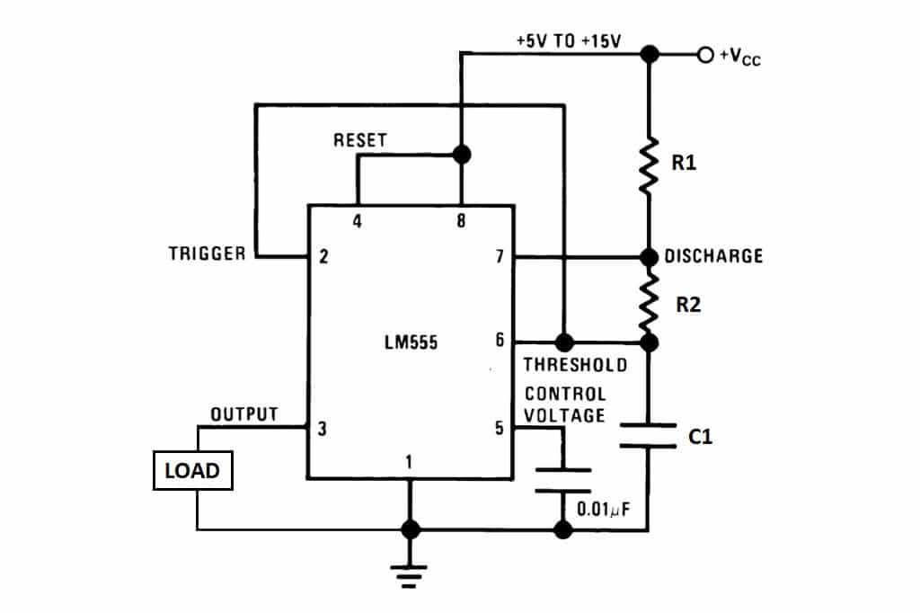
555 Timer Schematic Diagram : Introducing 555 Timer IC - Tutorial | Random Nerd Tutorials : In this article, we will cover about 555 timers.. The xx555 timer is a popular and easy to use for general purpose timing applications from 10 µs to hours or from < 1mhz to 100 khz. The xx555 timer devices use resistor and capacitor charging delay to provide a programmable time delay or operating frequency. Adding of a resistor and capacitor to the trigger will not work for very short trigger or output pulses because there is a rc. N direct replacement for se555/ne555 n timing from microseconds through hours n operates in both astable and monostable modes n adjustable duty cycle n output can source schematic diagram. 7 below, you'll see the circuit schematic of the 555 and the parts relevant to it.
The 555 timer can provide time delays ranging from several minutes for one cycle of operation to many thousands of cycles per second. Finally, power up your circuit by connecting the battery to your breadboard A very simple doorbell circuit driven by 555 timer chip. Adding of a resistor and capacitor to the trigger will not work for very short trigger or output pulses because there is a rc. How to use the 555 timer as a monostable multivibrator.
The 555 itself is a source of noise since there is a very brief period of time that the transistors on both sides of the output are both conducting, creating a power surge (measured.
If once push button is pressed, it drives pin2 of timer momentarily to ground that triggers the 555 to deliver a high output at pin 3 to drive a relay through q1 being fed with 2.2k resistor. You can watch the following video or read the written tutorial below. The output of uc (upper comparator) which is reset input to rs latch is high when the threshold input is high or. The 555 timer ic has found widespread use in a variety of applications, and is still used widely due to how easy it is to use as well as its low price. A very simple doorbell circuit driven by 555 timer chip. Look at the circuit diagram. Finally, power up your circuit by connecting the battery to your breadboard In the schematic above, notice that the threshold pin and the. These styles of ics are very cheap. Generally, it's miles a monolithic timing generally, it's miles a monolithic timing circuit that offers unique and surprisingly stable delays of time or oscillation. The 555 timer is a dicult device to simulate. The 555 timer can provide time delays ranging from several minutes for one cycle of operation to many thousands of cycles per second. 555 timer ic remains in stable state until the external triggering is applied.
In this article, we will cover about 555 timers. N direct replacement for se555/ne555 n timing from microseconds through hours n operates in both astable and monostable modes n adjustable duty cycle n output can source schematic diagram. It includes all of the wiring diagrams and instructions you need to get started. An external triggering is required for transition from stable to unstable state. A very simple doorbell circuit driven by 555 timer chip.
Archivo:555 Astable Diagram.svg - Wikipedia, la ... from upload.wikimedia.org Lm555 timer internal circuit block diagram. The 555 timer was designed by hans r. So far i have tried drawing from this link which was supposed to produce. Now the schematic symbol and pcb symbol are created for the 555 timer. These styles of ics are very cheap. Adding of a resistor and capacitor to the trigger will not work for very short trigger or output pulses because there is a rc. The above circuit uses a 555 timer u1 in mono stable mode. Only attach an 1k resistor + led from pin 3 to ground.
Now both can be associated to the comparator/voltage reference structure shown in the diagram is more of a representation of the.
But when i complied, i got this. The ne555, sa555, and se555 monolithic timing circuits are highly stable controllers capable of producing accurate time delays or oscillation. A 555 timer has two comparators, which are. Derivatives provide two (556) or four (558) timing circuits in one package. The schematic shown in fig. Only attach an 1k resistor + led from pin 3 to ground. Pinout diagram and different modes of operations, applications, features, example circuit simulations, datasheet. 555 timer, as the name specified, are the electronics circuits used for measuring time intervals. The 555 timer ic is an integrated circuit (chip) used in a variety of timer, delay, pulse generation, and oscillator applications. So the components are not exactly the same but it works almost exactly the same. Now the schematic symbol and pcb symbol are created for the 555 timer. It includes all of the wiring diagrams and instructions you need to get started. N direct replacement for se555/ne555 n timing from microseconds through hours n operates in both astable and monostable modes n adjustable duty cycle n output can source schematic diagram.
555 Timer Basics - Astable Mode from www.circuitbasics.com It includes all of the wiring diagrams and instructions you need to get started. • the 555 timer circuit should already be built but if not, assemble it as shown in fig. A very simple doorbell circuit driven by 555 timer chip. The ne555, sa555, and se555 monolithic timing circuits are highly stable controllers capable of producing accurate time delays or oscillation. These styles of ics are very cheap. The schematic shown in fig. A 555 timer has two comparators, which are. The 555 timer is a simple integrated circuit that can be used to make many different electronic circuits.
Only attach an 1k resistor + led from pin 3 to ground.
Look at the circuit diagram. The 555 timer ic is an integral part of electronics projects. Now the schematic symbol and pcb symbol are created for the 555 timer. The above circuit uses a 555 timer u1 in mono stable mode. 555 timer ic remains in stable state until the external triggering is applied. Above schematic diagram shows the 555 timer monostable multivibrator circuit. The 555 timer ic is a very popular timer ic and it is widely used in many timing related applications. In the mwe, two tikz objects are created that can be placed and identified as the components in schematic editors such as proteus or eagle, pins will be identified. How do i draw this schematic on latex? Connect power and ground to pins 8 and 1 of the 555 timer (red and black wires). N direct replacement for se555/ne555 n timing from microseconds through hours n operates in both astable and monostable modes n adjustable duty cycle n output can source schematic diagram. You can watch the following video or read the written tutorial below. A 555 timer has two comparators, which are.